
How collapsing bubbles and cold plasma break a carbon–fluorine bond
Two non-thermal routes to destroying PFAS were reported this week. Both work by concentrating the target at a bubble surface, and both prove it the only honest way — by measuring the fluoride that comes off.
Two groups at Germany's Helmholtz-Zentrum Dresden-Rossendorf reported on 25 August that they had destroyed PFAS in water using two entirely different non-thermal methods. Neither uses a furnace, a catalyst, or an added chemical. Both are worth understanding at the level of the bond, because the bond is the whole problem.
Why PFAS survive everything else
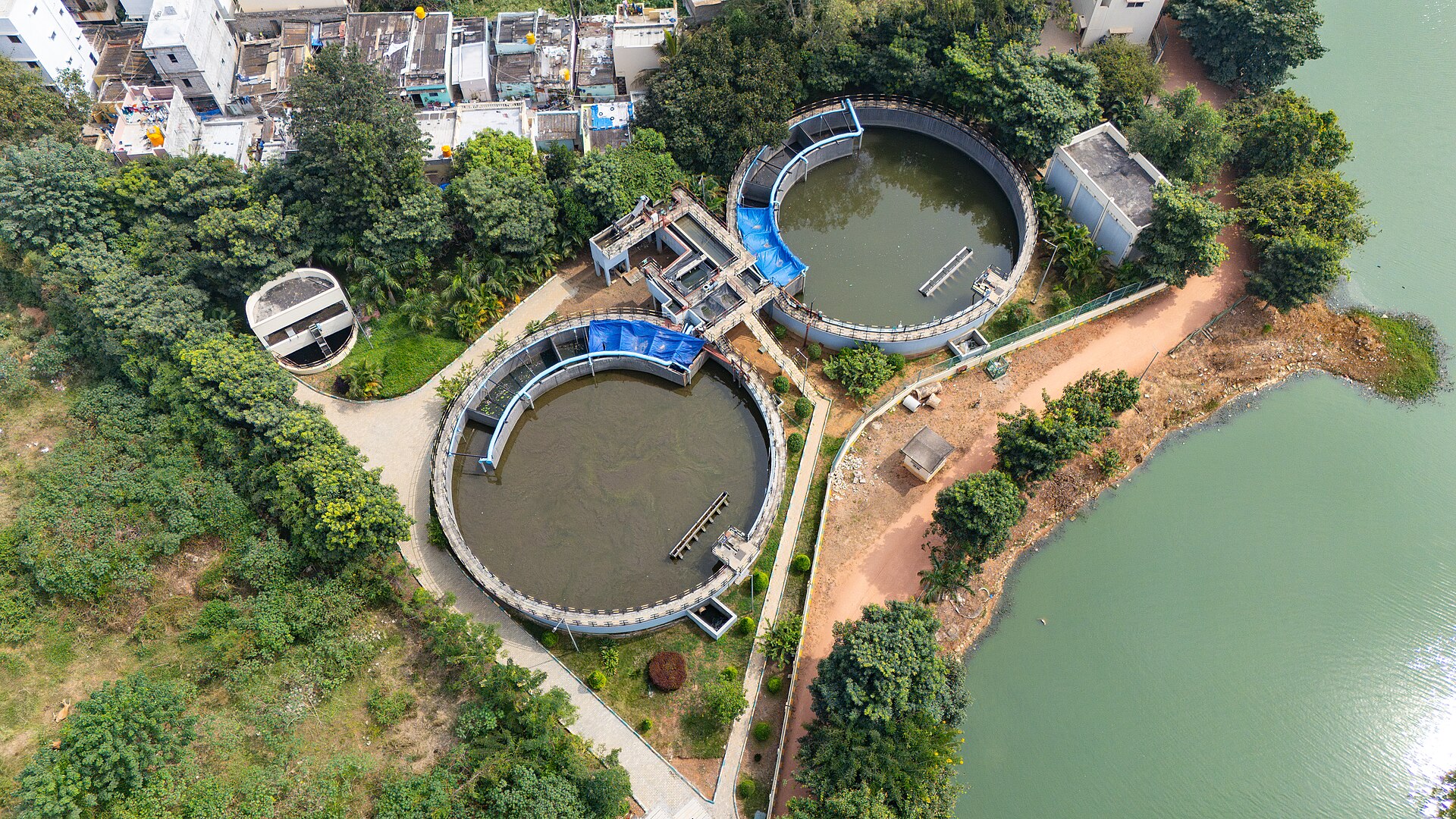
A carbon–fluorine bond is among the strongest single bonds in organic chemistry. Bacteria in an activated sludge tank cannot cleave it. Chlorination does not touch it. A conventional wastewater plant passes PFAS through essentially unchanged and discharges them.
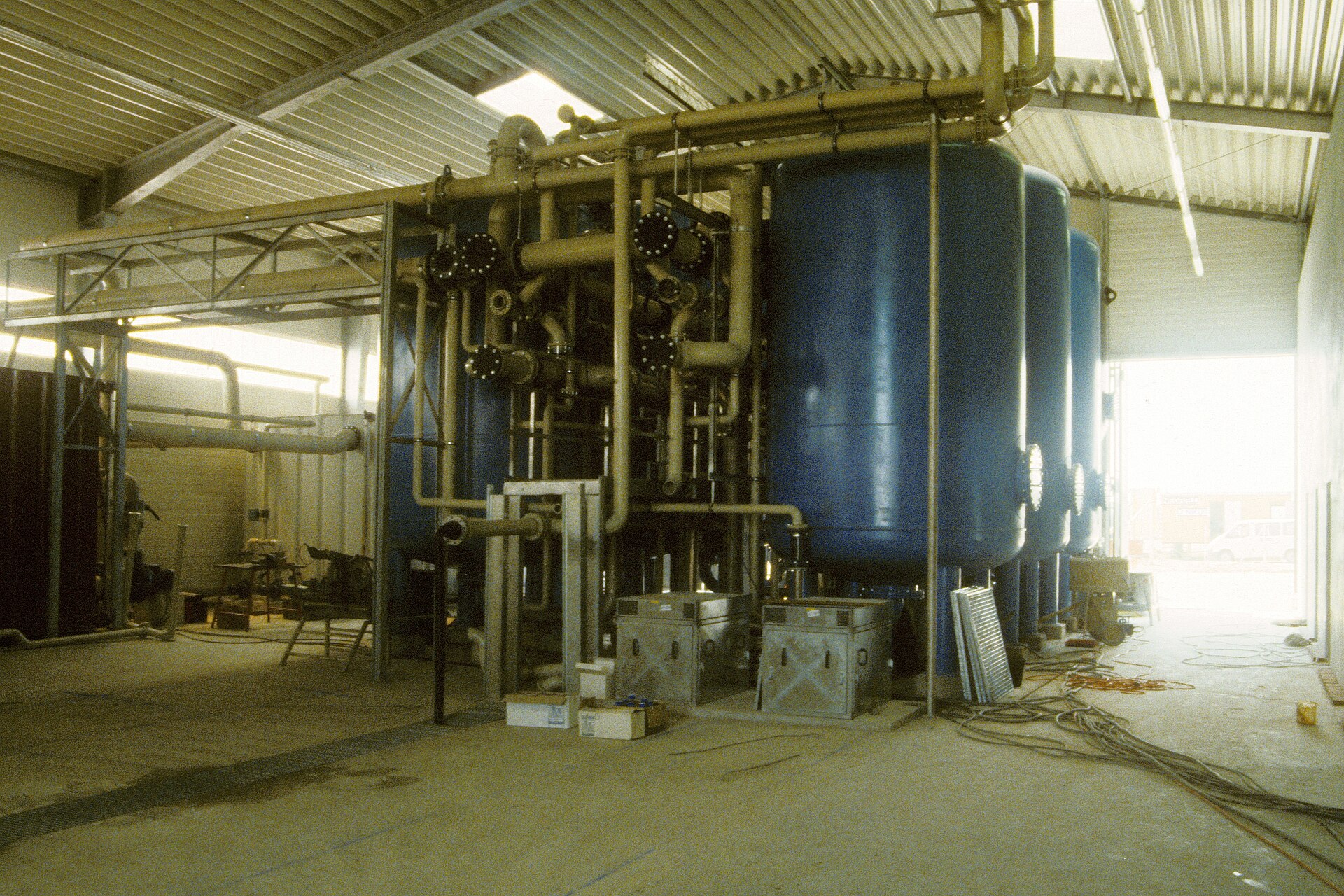
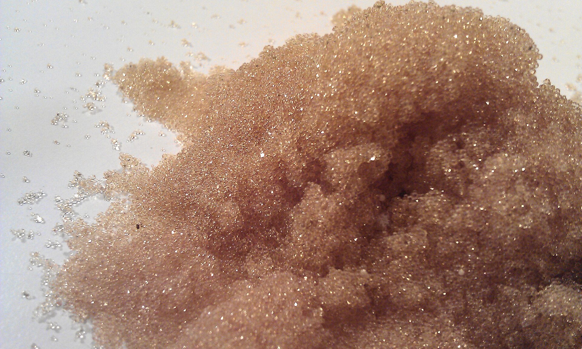
So the industry does the next best thing: it moves the molecules. Granular activated carbon and ion-exchange resin both adsorb PFAS out of water and onto a solid. The water leaves clean. The solid leaves loaded.
Method 1 — collapsing bubbles
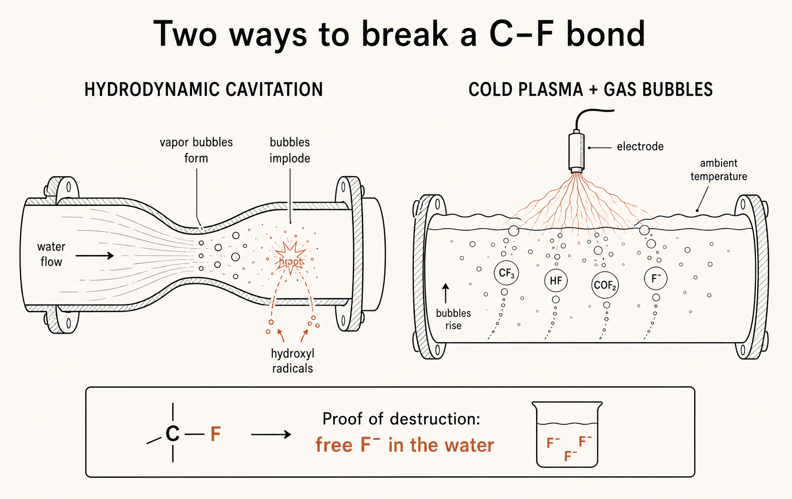
Hydrodynamic cavitation is a plumbing phenomenon before it is a chemistry one. Force water through a constriction and its velocity rises; as velocity rises, local pressure falls. Drop it below the vapour pressure of water at that temperature and the liquid boils cold — tiny vapour cavities form in the flow.
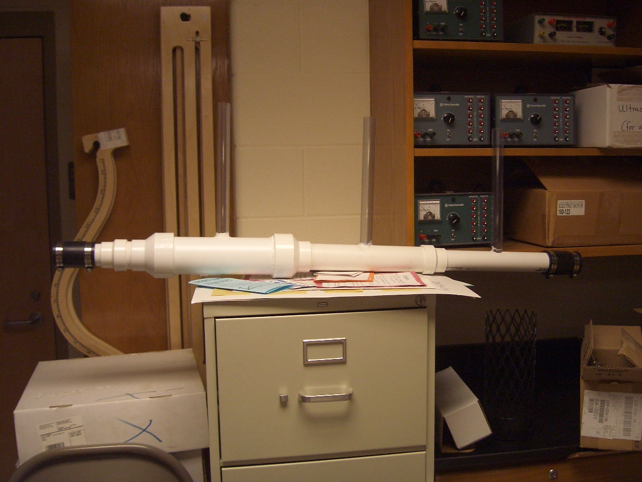
Downstream the channel widens, velocity drops, pressure recovers — and every one of those cavities implodes. The collapse is violent and extremely local: transient temperatures and pressures far above the bulk conditions, confined to a bubble a few micrometres across, generating hydroxyl radicals at the bubble–water interface.
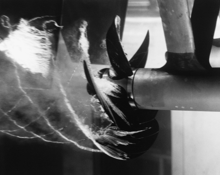
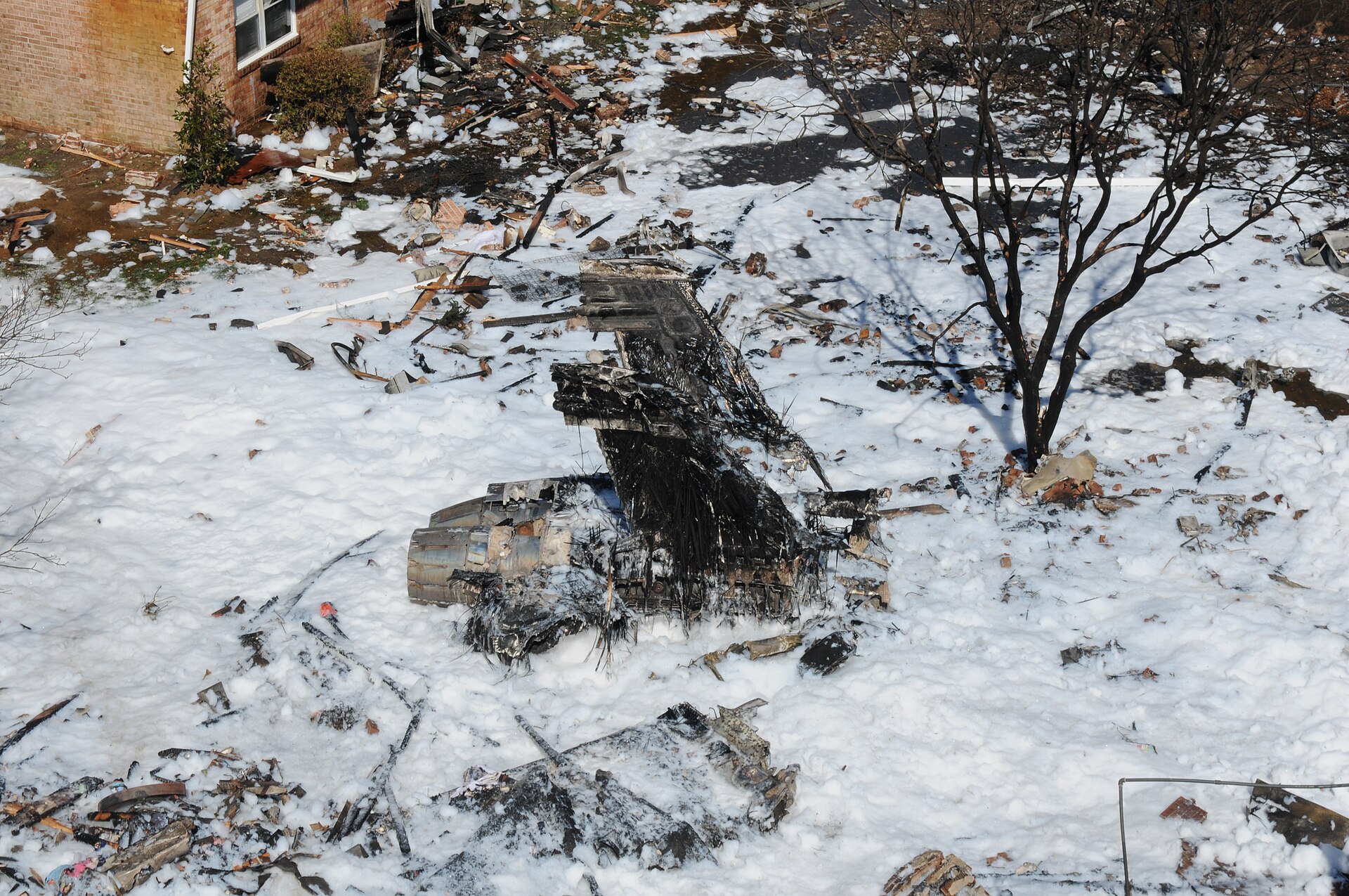
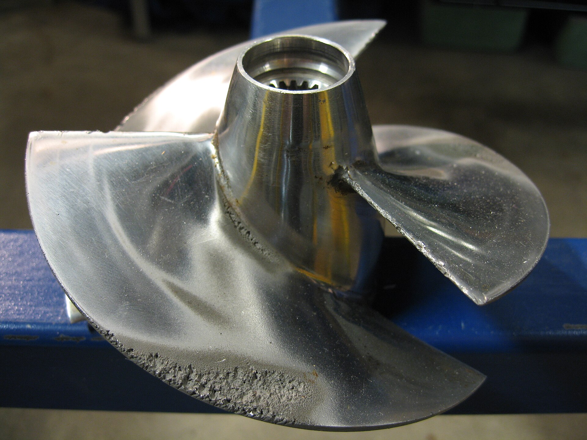
Engineers have known about this energy density for a century, because it destroys hardware.
PFAS are surface-active. They migrate to the bubble–water interface, which is precisely where the radicals are produced and where the collapse energy is concentrated. That coincidence is why cavitation works better on PFAS than the bulk radical concentration would suggest.
Method 2 — cold plasma over the water
The second method applies a high voltage to a gas sitting above the contaminated water. The discharge ionises the gas into a non-thermal plasma: the free electrons are extremely energetic, but they are so few and so light that the gas itself stays close to room temperature. You get radical chemistry without heat.
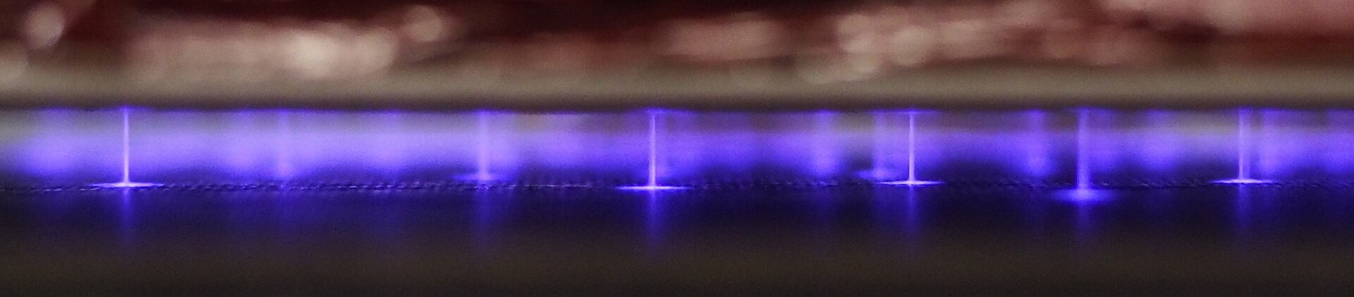

The HZDR group led by Amit Kumar adds a dispersion step: gas bubbles are driven up through the water, and PFAS — again, because they are surfactants — accumulate on the rising bubble surfaces. The plasma-generated species then meet a concentrated film of target molecules at the interface rather than a dilute solution. Ambient temperature, ambient pressure, no added catalyst or oxidant.
The proof: free fluoride
The reason this work is credible is not the reactor. It is the analyte.
An independent analysis at the Helmholtz Centre for Environmental Research confirmed fluoride release for both methods. Defluorination is the honest metric in this field, and it is the one that separates destruction from a very convincing removal.
Where this sits in the toolkit
Destruction is a crowded field: electrochemical oxidation, supercritical water oxidation, UV-sulfite reduction, sonolysis, and now these. What distinguishes the HZDR pair is the absence of high temperature and high pressure, which is what makes a modular on-site unit imaginable rather than a regional thermal facility.
The counterweight is matrix effects. The ITRC — the standard technical reference for PFAS treatment — is direct that several non-thermal destruction methods remain largely unproven on real landfill leachate, where dissolved organics and co-contaminants compete for every radical produced.
Short-chain PFAS and precursors also remain awkward for most of these routes — they are less surface-active, so the interface-concentration trick that makes both HZDR methods efficient works less well on exactly the compounds regulators are moving toward.
What to watch
Three numbers decide whether either method leaves the bench: defluorination percentage (not removal percentage), energy per unit of water at a stated starting concentration, and performance in a real matrix rather than clean water. None of them appear in a press release. All of them appear in a pilot report.
References and image credits›
- 01ScienceDaily / HZDR — Two new ways to destroy forever chemicals
- 02ITRC — PFAS-1, Section 12: Treatment Technologies
- 03U.S. EPA — PFAS Innovative Treatment Team (PITT)
- 04PNAS — How to destroy forever chemicals for good
U.S. Navy photo, public domain · P e z i, Wikimedia Commons, CC BY-SA 3.0 · Tomásdearg92, Wikimedia Commons, CC BY-SA 3.0 · Nader Moussa, Wikimedia Commons, CC BY-SA 3.0 · U.S. Navy, public domain · Erik Axdahl, Wikimedia Commons, CC BY-SA 2.5 · Devansh.sharma, Wikimedia Commons, CC BY-SA 4.0 · LLHZ2805, Wikimedia Commons, CC BY-SA 4.0 · Wikimedia Commons, CC BY-SA · PhilMacD, Wikimedia Commons, CC BY-SA 3.0 · John Haynes, Wikimedia Commons, CC BY-SA 2.0